I've needed a welding table for quite a while. I happened upon this one at a local shop - destined for the scrap yard. It's not exactly what I would have built had I made one from scratch, but the price was right 😁. Follow along as I turn it into a mobile workstation by adding storage, a vise, casters, and level feet.
 |
| Sitting in the shop after I brought her home |
Plug 'em up!
 |
| That's a top-quality item |
Since the table had these "holes" plasma cut through the top, I assume it had a vise mounted here previously. The first order of business was to fill these things in. I clamped an aluminum backing plate to the underside of the table and filled the holes using my MIG welder. A backing plate gives the weld puddle something to lay against so that it stays in place. Aluminum and brass are nice materials to use when working with steel since the two won't fuse together.
 |
| Aluminum backing plate |
I couldn't reach the centermost hole with a clamp, but luckily I was able to hold my aluminum plate in place with some welding magnets.
 |
| Welding magnets to the rescue |
 |
| After welding |
After the holes were filled with weld (making sure that they were filled above flush with no undercuts), I had to grind them down to flush with the tabletop. I roughed them out with a 40-grit grinding wheel in the angle grinder and then finished up with an 80-grit flap disc. While I had the flap disc on the grinder, I ran around the table and knocked down every booger and sharp spot that I found.
 |
| After smoothing |
Vise Vise Baby
Now that I had the top smoothed out, I decided to mount my newly restored Reed vise to it. If you haven't seen it, I documented the restoration of this vise here. You may notice two details in the next picture. There are a bunch of abandoned hole locations marked on the top. Because of the supports under the top, It took me a few attempts to find a spot that was close to the corner and still allowed all four bolts to be used. Also, the holes aren't square to the edge of the table. I learned when mocking up the vise that when its swivel base is locked, its jaws aren't square to it's mounting holes. I decided that I'd rather have a square vise than square bolt holes.
I drilled the holes for clearance with 1/2" bolts, and I ended up using carriage bolts to mount the vise. I really like the clean look they create, and thankfully they didn't try to spin on me while I was tightening them up.
Time for a barely-related side story... I recently learned that I, much like you, have been using keyless drill chucks incorrectly for millennia. I didn't believe it either, but I've seen the error in my ways and I'm here to show you the light. Next time you're using your drill, tighten the chuck as you normally would. Once it's tight, spin the barrel in the opposite direction until it clicks. If you feel / hear it click, you have a locking chuck and you just increased it's holding power! If it just loosens, pick up your freshly broken drill bit and feel free to curse my name.
I cut the tubing in half to get two roughly 4 5/8" long pieces, and then set them up in the bandsaw so that each piece would be split lengthwise. The pieces were set at an angle so that they would taper from 2" tall down to 1" tall (approximately).
With the pieces all split in half, I cleaned up all the edges with the flap disc and rounded the corners over while I was at it. I put the pieces in the vise, drilled and then tapped them to accept M8 x 1.25 screws (Yeah, I'm not happy about metric either, but it's what I could get my hands on easily). With the holes threaded, I could bolt on the casters.
It was now time to mount the caster brackets to the table. Using shims between the legs and the floor, I raised the legs about 1/2" above the floor. I noticed that the table was a little twisted, so I settled on getting the center of the table level and cut down on its teetering.
Next, I used the flap wheel to knock the paint off the legs roughly where the new casters were going to be mounted. Then, it was a simple matter of holding the bracket in place and welding it in place. I rested the casters on the floor while putting the brackets in place so they would keep the top level when on the wheels.
I repeated the same process three more times and I wound up with a wheely easy-to-move table.
As you may have noticed, I mounted the casters on the inside of the legs - my shins will thank me later.
Now that the table was on its casters, it was time to add leveling feet. I sliced off some 3/8" x 2 1/2" bar that I've been using up over the years. These blanks were then cleaned up on the mill so that they would all be the same width, and have some taper on the ends to match the inside of the channel that makes the table's legs.
While they were still together, I clamped them to the table of my baby drill press, drilled a pilot hole, and then a 21/64" hole for the upcoming 3/8" - 16 tap. Bonus points if anyone notices where I screwed up with the foot mounts. Thank goodness it's easy to fill gaps with a MIG welder!
I salvaged these feet from our old washer on its way to the scrap yard a while back
With everything assembled, I cranked the feet to the same height and welded them in place inside the channel. It was a similar process to the caster mounts. I placed them at such a height that they can pick the casters off of the ground by about 1/16", and just about tuck completely out of the way when I'm rolling the table around.
The heat from welding loosened up the thread locker that was holding the nuts in place. I was a little bent out of shape about it, until I realized that I could then take the nuts off, and place them on the top of the threaded portion of the feet. A little tack weld holds them in place now, and I can use a socket on a ratchet (or impact gun) to raise and lower the feet - way easier than an open-end wrench!
I drilled the holes for clearance with 1/2" bolts, and I ended up using carriage bolts to mount the vise. I really like the clean look they create, and thankfully they didn't try to spin on me while I was tightening them up.
Time for a barely-related side story... I recently learned that I, much like you, have been using keyless drill chucks incorrectly for millennia. I didn't believe it either, but I've seen the error in my ways and I'm here to show you the light. Next time you're using your drill, tighten the chuck as you normally would. Once it's tight, spin the barrel in the opposite direction until it clicks. If you feel / hear it click, you have a locking chuck and you just increased it's holding power! If it just loosens, pick up your freshly broken drill bit and feel free to curse my name.
 |
| New holes for the vise |
 |
| In her new home |
Caster? I hardly know her!
Now that I had a decent work surface, I could continue my project by making a set of brackets to hold some swivel casters that I had on the shelf. I also had about 9 1/4" of this 3" x 1/4" wall square tubing lying around.
 |
| Caster materials |
I cut the tubing in half to get two roughly 4 5/8" long pieces, and then set them up in the bandsaw so that each piece would be split lengthwise. The pieces were set at an angle so that they would taper from 2" tall down to 1" tall (approximately).
 |
| Cutting the tube in half |
 |
| I'm the king of sketchy set-ups! |
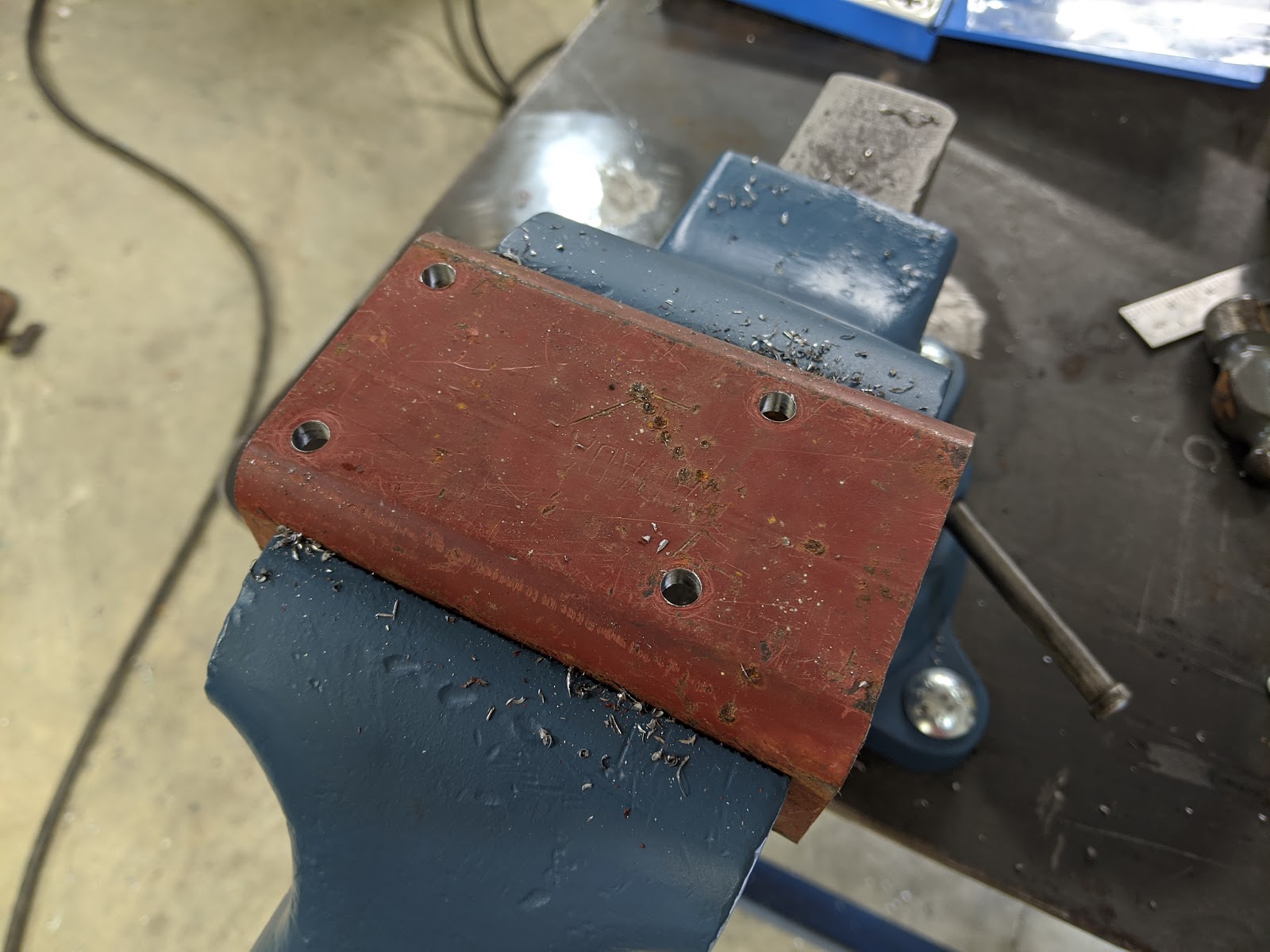
With the pieces all split in half, I cleaned up all the edges with the flap disc and rounded the corners over while I was at it. I put the pieces in the vise, drilled and then tapped them to accept M8 x 1.25 screws (Yeah, I'm not happy about metric either, but it's what I could get my hands on easily). With the holes threaded, I could bolt on the casters.
 |
| All drilled |
 |
| Tapping |
 |
| All four caster mounts |
It was now time to mount the caster brackets to the table. Using shims between the legs and the floor, I raised the legs about 1/2" above the floor. I noticed that the table was a little twisted, so I settled on getting the center of the table level and cut down on its teetering.
Next, I used the flap wheel to knock the paint off the legs roughly where the new casters were going to be mounted. Then, it was a simple matter of holding the bracket in place and welding it in place. I rested the casters on the floor while putting the brackets in place so they would keep the top level when on the wheels.
I repeated the same process three more times and I wound up with a wheely easy-to-move table.
 |
| All four casters in place |
As you may have noticed, I mounted the casters on the inside of the legs - my shins will thank me later.
Four feet from the finish line
Now that the table was on its casters, it was time to add leveling feet. I sliced off some 3/8" x 2 1/2" bar that I've been using up over the years. These blanks were then cleaned up on the mill so that they would all be the same width, and have some taper on the ends to match the inside of the channel that makes the table's legs.
 |
| Cleaning up the foot mounts in the mill |
While they were still together, I clamped them to the table of my baby drill press, drilled a pilot hole, and then a 21/64" hole for the upcoming 3/8" - 16 tap. Bonus points if anyone notices where I screwed up with the foot mounts. Thank goodness it's easy to fill gaps with a MIG welder!
 |
| Drilling the foot mounts while all clamped together |
 |
| Tapping the foot mounts |
I salvaged these feet from our old washer on its way to the scrap yard a while back
 |
| Ready to be welded in place |
With everything assembled, I cranked the feet to the same height and welded them in place inside the channel. It was a similar process to the caster mounts. I placed them at such a height that they can pick the casters off of the ground by about 1/16", and just about tuck completely out of the way when I'm rolling the table around.
The heat from welding loosened up the thread locker that was holding the nuts in place. I was a little bent out of shape about it, until I realized that I could then take the nuts off, and place them on the top of the threaded portion of the feet. A little tack weld holds them in place now, and I can use a socket on a ratchet (or impact gun) to raise and lower the feet - way easier than an open-end wrench!
 |
| All done...ish |
Shelve it where the sun don't shine
Now that I had all the planned metalwork for the table out of the way, I shifted my focus to storage and usability. I cut a scrap piece of 3/4" plywood to form a shelf inside the angle iron members at the bottom. This shelf now houses an intermediate chest that has sat unused for years. It now houses my grinding wheels, grinder wrenches, a large engineers hammer, layout and marking tools, MIG pliers, etc. - everything that I would normally use at this table. LEAN, baby! This shelf is also proving to be a nice catch-all for miscellaneous stuff that hasn't found a permanent home in the shop yet.
 |
| All done |
If the primer, bare metal, and welding smoke ever starts to bother me, I'll consider cleaning up and painting the new additions. Until then, I plan on using this bad boy for work!
This was a rewarding project, even if it took longer than I had expected to wrap up. It allowed me to start using my old vise again, and now I have a decent place to do metalwork or spread out parts for other projects. Anyone want to take a guess at what this upcoming project is?
 |
| An upcoming project... |
Sorry for all the puns, I guess I'm channeling my inner Bob Belcher tonight.
Thanks for reading!


