Monday, April 27, 2020

Welding Table

I've needed a welding table for quite a while.  I happened upon this one at a local shop - destined for the scrap yard.  It's not exactly what I would have built had I made one from scratch, but the price was right 😁.  Follow along as I turn it into a mobile workstation by adding storage, a vise, casters, and level feet.

Sitting in the shop after I brought her home


Plug 'em up!


That's a top-quality item

Since the table had these "holes" plasma cut through the top, I assume it had a vise mounted here previously.  The first order of business was to fill these things in.  I clamped an aluminum backing plate to the underside of the table and filled the holes using my MIG welder.  A backing plate gives the weld puddle something to lay against so that it stays in place.  Aluminum and brass are nice materials to use when working with steel since the two won't fuse together.


Aluminum backing plate

I couldn't reach the centermost hole with a clamp, but luckily I was able to hold my aluminum plate in place with some welding magnets.


Welding magnets to the rescue


After welding

After the holes were filled with weld (making sure that they were filled above flush with no undercuts), I had to grind them down to flush with the tabletop.  I roughed them out with a 40-grit grinding wheel in the angle grinder and then finished up with an 80-grit flap disc.  While I had the flap disc on the grinder, I ran around the table and knocked down every booger and sharp spot that I found.

After smoothing


Vise Vise Baby


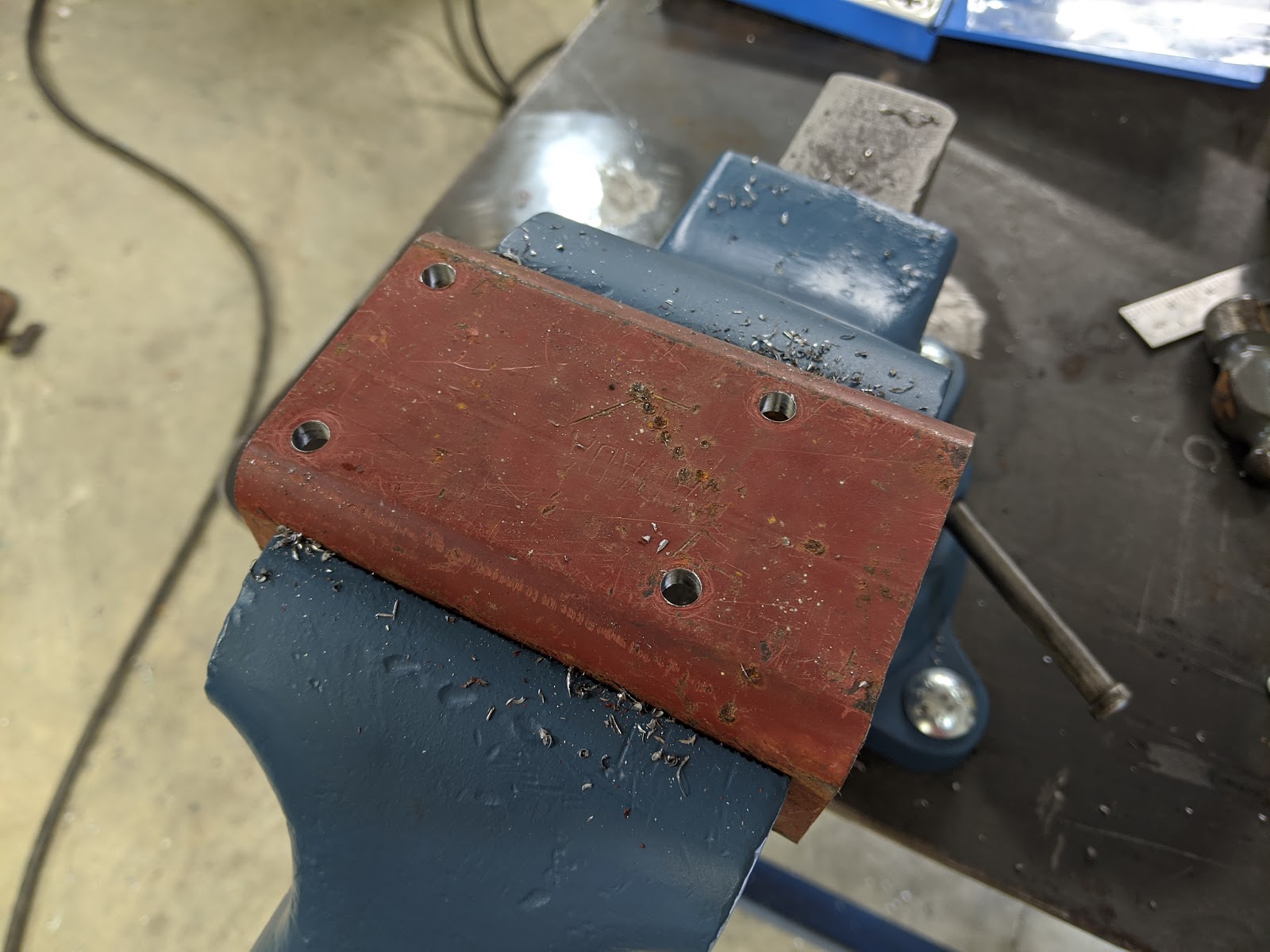
Now that I had the top smoothed out, I decided to mount my newly restored Reed vise to it.  If you haven't seen it, I documented the restoration of this vise here.  You may notice two details in the next picture.  There are a bunch of abandoned hole locations marked on the top.  Because of the supports under the top, It took me a few attempts to find a spot that was close to the corner and still allowed all four bolts to be used.  Also, the holes aren't square to the edge of the table.  I learned when mocking up the vise that when its swivel base is locked, its jaws aren't square to it's mounting holes.  I decided that I'd rather have a square vise than square bolt holes.

I drilled the holes for clearance with 1/2" bolts, and I ended up using carriage bolts to mount the vise.  I really like the clean look they create, and thankfully they didn't try to spin on me while I was tightening them up.

Time for a barely-related side story...  I recently learned that I, much like you, have been using keyless drill chucks incorrectly for millennia.  I didn't believe it either, but I've seen the error in my ways and I'm here to show you the light.  Next time you're using your drill, tighten the chuck as you normally would.  Once it's tight, spin the barrel in the opposite direction until it clicks.  If you feel / hear it click, you have a locking chuck and you just increased it's holding power!  If it just loosens, pick up your freshly broken drill bit and feel free to curse my name.

New holes for the vise

In her new home


Caster?  I hardly know her!


Now that I had a decent work surface, I could continue my project by making a set of brackets to hold some swivel casters that I had on the shelf.  I also had about 9 1/4" of this 3" x 1/4" wall square tubing lying around.


Caster materials


I cut the tubing in half to get two roughly 4 5/8" long pieces, and then set them up in the bandsaw so that each piece would be split lengthwise.  The pieces were set at an angle so that they would taper from 2" tall down to 1" tall (approximately).


Cutting the tube in half


I'm the king of sketchy set-ups!

With the pieces all split in half, I cleaned up all the edges with the flap disc and rounded the corners over while I was at it.  I put the pieces in the vise, drilled and then tapped them to accept M8 x 1.25 screws (Yeah, I'm not happy about metric either, but it's what I could get my hands on easily).  With the holes threaded, I could bolt on the casters.


All drilled


Tapping


All four caster mounts

It was now time to mount the caster brackets to the table.  Using shims between the legs and the floor, I raised the legs about 1/2" above the floor.  I noticed that the table was a little twisted, so I settled on getting the center of the table level and cut down on its teetering.

Next, I used the flap wheel to knock the paint off the legs roughly where the new casters were going to be mounted.  Then, it was a simple matter of holding the bracket in place and welding it in place.  I rested the casters on the floor while putting the brackets in place so they would keep the top level when on the wheels.

I repeated the same process three more times and I wound up with a wheely easy-to-move table.


All four casters in place

As you may have noticed, I mounted the casters on the inside of the legs - my shins will thank me later.

Four feet from the finish line


Now that the table was on its casters, it was time to add leveling feet.  I sliced off some 3/8" x 2 1/2" bar that I've been using up over the years.  These blanks were then cleaned up on the mill so that they would all be the same width, and have some taper on the ends to match the inside of the channel that makes the table's legs.

Cleaning up the foot mounts in the mill

While they were still together, I clamped them to the table of my baby drill press, drilled a pilot hole, and then a 21/64" hole for the upcoming 3/8" - 16 tap.  Bonus points if anyone notices where I screwed up with the foot mounts.  Thank goodness it's easy to fill gaps with a MIG welder!


Drilling the foot mounts while all clamped together

Tapping the foot mounts

I salvaged these feet from our old washer on its way to the scrap yard a while back


Ready to be welded in place

With everything assembled, I cranked the feet to the same height and welded them in place inside the channel.  It was a similar process to the caster mounts.  I placed them at such a height that they can pick the casters off of the ground by about 1/16", and just about tuck completely out of the way when I'm rolling the table around.

The heat from welding loosened up the thread locker that was holding the nuts in place.  I was a little bent out of shape about it, until I realized that I could then take the nuts off, and place them on the top of the threaded portion of the feet.  A little tack weld holds them in place now, and I can use a socket on a ratchet (or impact gun) to raise and lower the feet - way easier than an open-end wrench!


All done...ish

Shelve it where the sun don't shine


Now that I had all the planned metalwork for the table out of the way, I shifted my focus to storage and usability.  I cut a scrap piece of 3/4" plywood to form a shelf inside the angle iron members at the bottom.  This shelf now houses an intermediate chest that has sat unused for years.  It now houses my grinding wheels, grinder wrenches, a large engineers hammer, layout and marking tools, MIG pliers, etc. - everything that I would normally use at this table.  LEAN, baby!  This shelf is also proving to be a nice catch-all for miscellaneous stuff that hasn't found a permanent home in the shop yet.

All done

If the primer, bare metal, and welding smoke ever starts to bother me, I'll consider cleaning up and painting the new additions.  Until then, I plan on using this bad boy for work!

This was a rewarding project, even if it took longer than I had expected to wrap up.  It allowed me to start using my old vise again, and now I have a decent place to do metalwork or spread out parts for other projects.  Anyone want to take a guess at what this upcoming project is?

An upcoming project...

Sorry for all the puns, I guess I'm channeling my inner Bob Belcher tonight.

Thanks for reading!

Tuesday, April 21, 2020

Firewood Processor Controller

I worked on this project about a year ago.  I realized recently that I had just enough pictures and a fuzzy enough memory to pull off a blog entry.  Enjoy...

A friend of mine has a firewood processor that was having some electrical issues last year.  The manufacturer didn't use an enclosure that was rated to be outside in the rain, so the inside was always damp and he was replacing components regularly because of corrosion and rust.

Original controller


Oh, the humanity!

It took some convincing, but he brought the machine over to my shop, and I got to work.  The plan was to keep the design of the controls the same, but to use higher quality components.  I started by making a parts list for the new controller, which included new pushbuttons and cable glands that would maintain the NEMA 4 rating of our new enclosure.

In case you don't know, NEMA is the National Electrical Manufacturers Association.  They created a standard that dictates how resistant electrical enclosures and other components are to the ingress of dust, water, and other things you won't want mixing with the pixies in there.  NEMA 4 basically means that when assembled correctly, it will be waterproof (within reason).

With our parts on order, it was time to figure out how the existing controller worked.  I spent some time rooting around in there, writing down connections between components and poking arounf with a multimeter.  It took a few tries, but I was able to sketch up a schematic that appeared to match the existing controller.

After the new parts were delivered, I had to transpose the schematic because the terminals were configured differently on the relay sockets. This involved comparing the old and new sockets with a multimeter and making a table that related the terminals on the two versions.  Then I had to redraw my schematic.

Final schematic, drawn with handiCAD
With my new schematic in hand, it was time to start building the new panel.  I started by mocking up the new relays and terminal blocks on a section of DIN rail, and laying it on the subpanel of the enclosure. I kept it towards the bottom of the panel because I would need room in the panel for the cables (all eight of them) to enter the enclosure, and also because the height of the relays would interfere with the pushbuttons.

Once I was happy with the locations of everything, I drilled and tapped two holes in the panel to mount the DIN rail.  I then screwed the rail onto the panel and snapped on the components.  I then drilled three 7/8" diameter holes in the front of the enclosure for the pushbuttons.  I kept the layout of the front identical to the old enclosure so that I wouldn't screw up my friend's muscle memory when he was running this thing later.

With the components in place, it was time to use my schematic to connect the components on the panel together with some 14 gauge THHN wire.

New controller before the notch was added.
In a prime example of my supreme planning prowess, I now had to disassemble what I had constructed so that I could add clearance in the subpanel for the eight cables to pass through.  I took the components off of the rail, and drilled two holes to serve as the inside corners of the area I was going to remove.  Then, I went to the bandsaw to cut from the edge to the holes, and then from hole to hole - making a nice notch with rounded inside corners.

After a little filing to smooth out the edges, it was almost time to reassemble - after I drilled holes in the back of the enclosure for the new cable glands.  I laid them out to be as close as possible so that the cables coming through them would fit neatly inside my newly cut notch.  With the holes drilled, I could install the cable glands, and reinstall the subpanel and all my components.

With the new controller assembled, it was time to remove the old one from the machine.  To maintain order, I labeled the cables as I removed them, and then unbolted the old box from the machine.  To maintain it's NEMA rating, the new enclosure needed to be mounted from the back into four threaded inserts that the manufacturer installed.  This meant making a pair of uprights with 1" angle iron, drilling matching holes, and welding them to the frame of the processor.

Octopuss.  The old enclosure can be seen in the background.
When mounting the new enclosure, I decided to lay it back at an angle.  I did this for two reasons: First, it felt more comfortable to me, so it seemed like a better choice from an ergonomic standpoint.  Secondly, after removing some of the ends of the cables due to corrosion, some of them didn't have quite enough slack to land in the box when it was perfectly upright.  Dang!

I had some cans of knock-off John Deere green spray paint that was a surprisingly close match to the paint on the machine, so I shot the new brackets with a few coats to keep the rust to a minimum.  After the paint had dried and I mounted the new controller, I used the schematic and my labels to land the cables in their new home.

Inside the new controller, after the install
It was all done.  Nothing left to do but test it.  Would it work?  Would it explode?  My friend came over to help me find out.  He fired the machine up, put it through its paces, and... it operated just as it should - what a relief!

Having lived with the previous, janky enclosure for a quite a while before, he was suspicious that this new box would hold up to the elements.  To put his mind at ease, we sprayed it with the garden hose for a few minutes (he seemed a little shocked at my testing methods).  We did find one very slow leak at one of the cable glands, thanks to a burr on the edge of the hole, but that was a breeze to fix.  Once it was reinstalled and tightened up, the whole enclosure proved to be tighter than a clam with lockjaw.

Its been a year, and as far as I know, it's still operating perfectly.

New controller in place
Thanks for reading!

Wednesday, April 15, 2020

Reed 204R Vise Restoration

"Restoring" this vise seemed like a nice little project to document on the blog.  It's a Reed model 204R, and having now disassembled it, I've learned that it is a marvelous piece of engineering.

After sitting for a few years
My dad had this vise in his shop for as long as I can remember.  I never thought to ask him where and when he got it since it was just always there.  In a last-ditch attempt to learn more about its origins, I asked my mom if she remembered when it came home.  She seems to think it belonged to my great grandfather, who gave it to my father at some point.  That'd be pretty neat if true.

I've been unable to find any markings on the vise that may indicate the year that it was manufactured, but the patent number on the casting indicates that it was poured after 1938.  P.S. I love the artwork in old patents like this.


Disassembly


All disassembled
Disassembly was surprisingly smooth.  Thankfully it turned out that all of the work that the vise needed was superficial and cosmetic.  There were, however, just enough dings and dents on the slide to require the use of a small jack to force out of the body (after removal of the lead screw - obviously).

Removing the lead screw from the slide was educational.  This vise uses a two-piece threaded ring to hold the what (appeared to be) a one-piece leadscrew / handle assembly in the slide.  A pin spanner would have made quick work of removing it, but I had to settle for a punch and hammer - and some caution.  After I got it removed and cleaned up, I was tickled to see that this ring was cast and machined as one piece. After machining it was split by fracturing it at a predefined location thanks to two thin sections cast into it.  Pretty clever use of the brittleness of the iron used.

After separating the vise from its swivel base, I noticed yet another slick design feature.  The swivel-lock stud is serrated, and it locks into a serrated pattern in the base.  The design requires far less force on the swivel lock handle, and makes it nearly impossible for the vise to swivel inadvertently - saving knuckles!  I also noticed that the stud on the swivel lock is a double lead thread, which is one of the few that I've seen outside of a book.

Swivel Lock, after a little clean-up


Stripping and Repainting


After disassembly, it was time to start stripping the decades-worth of rust and paint from its surfaces.  A wire cup in an angle grinder made quick work of this task, although it did start to slow down towards the end of the project...


Ooof

I'd like to think I got my money's worth out of that cup.  After I plucked the wires from my shirt, I ordered a replacement and was back up and running a few days later.

Once the paint and loose rust was removed with the grinder, all of the surfaces that were going to be repainted were shot with primer.  Then two fairly heavy coats of a deep blue that I had sitting on the shelf.  All rattle-can stuff - I'm curious to see how it holds up to the abuse that a vise typically sees.  If I'm feeling spunky one day, I may highlight the letters on the casting with some white paint and a fine brush.

After the paint was dry, but before it had a chance to really harden up, it was time to clean up the surfaces that were not supposed to have paint.  Some hand sanding with 100-grit in the nooks and crannies, and some time with the orbital sander on the large flat areas brought some shine back to those surfaces and knocked down the burrs and high spots.  They're certainly not polished - in fact, they still have the scars of decades worth of work, but all the pieces slide together as they should now.

The two handles were chucked up in the lathe and rotated to make sanding easier.  This worked very well and made quick work of cleaning them up.  I started with the wire cup, and then moved on to 100-grit paper, then 240-grit, and finally some high-abrasive polishing compound.  Again, not a mirror finish, but much better than what I started with - and it still gets to tell its story.

Just finishing up the handle on the lathe


All of the unpainted surfaces were all coated with Minwax Paste Finishing Wax to add some lubricity and slow down the formation of new rust.  Because of the threat of condensation, I've gotten into the habit of waxing just about all of the bare iron and steel in my shop.  It's great on woodworking tools like the table saw and bandsaw, and it seems to work well on polished handwheels, too.


Reassembly


After the paint had some time to cure, it was time to put it all back together.  This was pretty easy, just the reverse of how she came apart.


A little dab will do ya
To keep things moving smoothly, I added some grease to the running surfaces between the body and swivel base.  I also precoated the thrust-bearing surfaces and leadscrew with oil.  The vise has two holes for oiling, so I decided to forgo the grease and give it with what it wants.  If anyone knows more about what kind of lubrication these things like, please let me know in the comments.

The leadscrew went in smoothly, and the threaded retention ring was a breeze to install - although just like during disassembly, I needed to tap the ring around with a punch and a hammer, since I don't have a pin spanner.  Even so, adjusting out most of the backlash was no problem.  Once I was happy with it, I snugged up the set screw that prevents the retention ring from spinning, and that was it.

This was a fun little project and a great excuse to spend some time in the shop.  It's going to be a treat to start using this vise again.  Now I just need a solid bench to mount her on.


All done

Thanks for reading!


Sunday, December 23, 2018

Happy Holidays!

Because of the holidays and some other distractions, I've made little progress in the shop over the past few weeks. I'm definitely not complaining - Christmas is my favorite holiday of the year.

That being said, I feel that I've done enough that an update is in order, so... Here we go!

Car Door

The door handle broke on the misses car a few weeks ago, forcing her to use the outside handle to get out of the car. I "repaired" it... twice... to make it usable while we waited for the replacement. The first time I just used some nylon wire ties to reconnect the end of the cable to the handle. They promptly broke thanks to the subfreezing temperatures we were experiencing at the time.

That's a top quality item right there.
For my second attempt, I removed the entire handle with the bandsaw to make room and replaced it with a loop of 14 gauge copper wire.  As you can imagine, the boss was not amused - but it did the job while we waited for the replacement.

Luckily (for me), the replacement showed up and I put it in last weekend.  I've become an expert at removing the door panels in this car. I doubt I can put that on a résumé, though.


Wainscoting and Three Phase

As I've said before, my immediate goal for the shop is to get the back walls finished up. This will allow me to get started on installing my three phase wiring, and give me finished wall space for stuff to sit against. Who doesn't love pushing stuff up against walls?!

Throughout the weeks leading up to Christmas, and between wrestling the door panel on the car, I was able to get enough wainscoting and trim installed to allow me to hang panels and run some conduit.

I received my three pole breakers and receptacles late Friday - just in time to help the boss prepare for a craft show (she makes and sells handmade signs and Christmas ornaments).  I had made her some ornamental sleds a while back, so we wrapped them up among other things. Most of Saturday was spent trying to sell said crafts. It was a decent turnout, but much to my chagrin, my sleds didn't sell.

Still waiting for a home

The enclosure that houses the contactors and capacitors for my phase converter will be mounted to the wall between the single and three phase circuit breaker panels.  The idler lives underneath the stairs. I figure it will keep the noise down, and keep it out of the way. 

The three-phase panel and the converter are all surface mounted, so a pair of 3/4" thick battens were attached to the wall beneath them. This allowed me to mount everything securely without having to worry about lining anything up with the studs.

Single and three-phase panels, and future enclosure for the
phase converter. I really need to clean or repaint that cover!

Once I had everything spaced out and mounted, I removed the empty enclosure and replaced it with my temporary prototype enclosure. It's made of plywood (don't worry, I grounded it 😁), and is only there until I can get the holes cut in the metal enclosure for the voltmeters and start/stop buttons.

With the load center mounted, it was time for some conduit. I'm using 3/4" EMT for all my runs. I once heard someone say that no one should ever run 1/2" EMT since 3/4" is practically the same cost and has almost twice the cross-sectional area. That seems to have stuck with me.
You can see the bottom corner of the
plywood RPC enclosure here. Don't judge!

The left section of conduit runs around the perimeter of the shop and makes its way under the stairs.  The 10 horsepower idler is connected to the end of this run with flexible metal conduit, and it's all filled with four 10 gauge THHN. The fourth conductor is a dedicated ground. Relying on the conduit as a ground is just asking for trouble, so I'll be running ground conductors for All My Circuits™ (bonus points for anyone that gets that reference).

The middle section of conduit is currently empty. It heads to the far end of the shop and will eventually service the drill press and horizontal mill.  I'm still wrestling with exactly where these machines will live permanently so it may be a while before the other end of this run is completed and filled with wire.

The short section to the right is there temporarily so that I could both check out the new table saw, and balance my phase converter. When the new saw officially replaces the old one, I'll run some conduit up and across the ceiling to keep the cord off the floor.

Balancing the voltages on this phase converter took a while longer than I expected. I'm sure it could use some more tweaking, but I'm happy with it for now. With the table saw running unloaded, the voltages are all within about ±3% of each other. We'll see how they do with a heavier load on them - I may have to order some more run capacitors.  If there's any interest, I can expand farther on the phase converted from a design and build standpoint - just let me know in the comments.

Table Saw

Little helper cleaning out the new saw
The saw fired right up and it runs like a champ. There is a bit of what sounds like bearing noise coming from the saw, presumably from the fan end of the motor. I'll end up kicking off the drive belts at some point so I can pinpoint the noise.

Even with the crappy blade that was in it when I bought it, I can tell it has substantially more power than the delta its replacing. On a related note, if anyone's looking for a great saw at a reasonable price - I know a guy.

I'm really looking forward to building up the surrounding table so I can set this thing up and start using it!

Anyway, I'm just wrapping up day two of eleven of my Christmas / New Year break, so with any luck, there will be plenty updates coming.

Merry Christmas, happy new year and thanks for sticking around!

Sunday, December 9, 2018

Ita been a while

A lot has happened to me and my family in the past year and a half since my last post.  For anyone that doesn't know me, we lost my father to cancer about 14 months ago. As a child, he exposed me to using both my mind and my hands to solve problems, and is the reason that I do what I do today.  He was a great man, and I couldn't have asked for a better father, teacher or friend.

Obviously, It took time to get my butt back in gear (generally, and especially in the shop), but I think I've finally gotten back into the swing of things.  In the past few months, I've made some incredible headway in my shop.  Unfortunately, I neglected to take everybody else along for the ride.  So, let's play ketchup. Catsup? Catch up?  Yeah, catch up...


My shop (the building itself) has been occupying most of my free time lately, but its nearing completion. With the exception of one 2' section between two overhead doors, everything has been insulated, drywalled and painted.  When its all finished, the bottom 2 - 4 feet of the walls will be covered in wainscoting made from laminate floor, and the tops will have 4 rows of french cleats.  Everything else will be trimmed in 2 ½ x ¾ douglas fir.  I wanted the ceiling to be somewhat flexible (so that I can add/modify stuff up there), so I ended up ripping 4' x 8' sheets of melamine coated hardboard into large ceiling tiles, and suspending them on the bottom flanges of the wood I-beam ceiling joists.

My immediate goal is to finish the trim and cleats on the back walls.  Once that is complete,  I'll be setting my phase converter back up and running EMT and 14 gauge THHN out to where all the 3 phase machines will sit.  This includes a Hermle horizontal mill, a Delta Rockwell radial drill press, a Logan model 200 engine lathe (currently single phase, but will be converting), and (drum roll, please) my new table saw...

In the midst of removing some surface rust from the table
I just picked 'er up Wednesday.  It's a 1950 Delta Rockwell 10" cabinet saw with a 3HP motor - which should run circles around the Delta contractor saw I've been running for the last few years.  This thing also has a Biesemeyer style fence (branded Powermatic) with a 52" rip capacity.  She's missing the front door and the motor cover, but luckily there's a company in California (www.bellplasticsfabrication.com) that makes plastic reproductions of these parts.

To make the most of the saw and fence, I plan on making an extension table with a router lift, sitting on copious cabinets.  It'll probably end up being 4' x 8' or so.  I'll probably also end up making a 4' x 4' or 4' x 6' outfeed/assembly table on locking casters - complete with cabinets underneath.  Obviously, this is still all up in the air until I start building.

With any luck, a new to me 60-gallon compressor will be the next addition.  I traded a small MIG welder for this compressor with a friend of mine.  I should be picking it up in the next few days and will be placing it under the steps.  I ran the electric for the compressor before the drywall went up, so it should just be a matter of plugging it in.  Also under these steps live the idler for the phase converter (10 hp) and the dust collector.  I wanted to keep all the noisy stuff out of the way and behind a wall.

Also on the horizon will be moving my dad's tools into my shop.  A few of the smaller power and hand tools have already migrated, but there are still a lifetimes worth in his old shop.  There is also a truckload of stationary machinery that will be finding its way here.  These include a 6" jointer, 14" bandsaw, wood lathe, hollow chisel mortiser, contractor's saw, miter box, and a drum sander.

This seems like enough for now.  I'll be sure to provide regular content in the future.  Please leave questions in the comments section, and let me know what you'd like to see more of.  I really would like to share what I do with anyone that can learn from me.